| 2002 WRX Engine Control Module (ECM) I/O Signals |
| Content |
Pin |
Wire
Color |
Signal (V) |
Note |
Ignition SW ON
(Engine OFF) |
Engine ON (Idling) |
Crankshaft
position
sensor |
Signal (+) |
B2 |
W |
0 |
–7 — +7 |
Sensor output waveform |
| Signal (–) |
B11 |
G |
0 |
0 |
— |
| Shield |
B21 |
SB |
0 |
0 |
— |
Camshaft
position
sensor |
Signal (+) |
B1 |
R |
0 |
–7 — +7 |
Sensor output waveform |
| Signal (–) |
B10 |
B |
0 |
0 |
— |
| Shield |
B21 |
SB |
0 |
0 |
— |
Throttle
position
sensor |
Signal |
B7 |
Lg |
Fully closed: 0.2 — 1.0
Fully opened: 4.2 — 4.7 |
— |
Power
supply |
B9 |
Sb1 |
5 |
5 |
— |
Ground
(sensor) |
B19 |
RG |
0 |
0 |
— |
Rear
oxygen
sensor |
Signal |
B17 |
W |
0 |
0 — 0.9 |
— |
| Shield |
B26 |
SB |
0 |
0 |
— |
Ground
(sensor) |
B19 |
RG |
0 |
0 |
— |
| Heater |
C13 |
RW |
0 — 1.0 |
0 — 1.0 |
— |
Front oxygen
(A/F)
sensor
|
Sensor (+) |
D19 |
W |
2.8 — 3.2 |
2.8 — 3.2 |
Positive voltage to
sensor's (+) terminal |
| Sensor (–) |
D29 |
B |
2.4 — 2.7 |
2.4 — 2.7 |
Positive voltage to
sensor's (–) terminal |
| Shield |
D18 |
SB |
0 |
0 |
— |
| Heater 1 |
D4 |
W |
0 — 1.0 |
0 — 1.0 |
— |
| Heater 2 |
D5 |
W |
0 — 1.0 |
0 — 1.0 |
— |
Engine
Coolant
temp.
sensor |
Signal |
B18 |
BY |
1.0 — 1.4 |
1.0 — 1.4 |
After engine warmup |
Ground
(sensor) |
B19 |
RG |
0 |
0 |
— |
| Vehicle speed signal |
A1 |
GY |
0 or 5 |
0 or 5 |
Four 5V pulses for each front
differential revolution. 2,548
pulses per minute is 60 km/h. |
Mass air
flow (MAF)
sensor |
Signal |
E13 |
PL |
— |
0.3 — 4.5 |
— |
| Shield |
E8 |
SB |
0 |
0 |
— |
| Ground |
E7 |
BG |
0 |
0 |
— |
Intake air temperature
sensor signal |
B27 |
Br |
— |
— |
— |
Exhaust
gas tem-
perature
sensor |
Signal |
B16 |
WB |
— |
— |
— |
Ground
(sensor) |
B19 |
RG |
0 |
0 |
— |
Tumble
generator
valve
position
sensor
RH |
Signal |
B23 |
BrR |
Fully closed: 0.2 — 1.0
Fully opened: 4.2 — 4.7 |
— |
Power
supply |
B9 |
Sb1 |
5 |
5 |
— |
Ground
(sensor) |
B19 |
RG |
0 |
0 |
— |
Tumble
generator
valve
position
sensor
LH |
Signal |
B13 |
BrY |
Fully closed: 0.2 — 1.0
Fully opened: 4.2 — 4.7 |
— |
Power
supply |
B9 |
Sb1 |
5 |
5 |
— |
Ground
(sensor) |
B19 |
RG |
0 |
0 |
— |
Tumble generator valve
RH (open) |
E4 |
LG |
0 or 5 |
0 or 5 |
— |
Tumble generator valve
RH (close) |
E5 |
YG |
0 or 5 |
0 or 5 |
— |
Tumble generator valve
LH (open) |
E11 |
L |
0 or 5 |
0 or 5 |
— |
Tumble generator valve
LH (close) |
E10 |
LY |
0 or 5 |
0 or 5 |
— |
Wastegate control
solenoid valve |
D24 |
BW |
10 — 13 |
13 — 14 |
— |
| Starter switch |
A16 |
Y |
0 |
0 |
Cranking: 8 — 14 |
| A/C switch |
A2 |
LY |
ON: 10 — 13
OFF: 0 |
ON: 13 — 14
OFF: 0 |
— |
| Ignition switch |
A5 |
GR |
10 — 13 |
13 — 14 |
— |
| Neutral position switch |
A8 |
WB |
ON: 12±0.5
OFF: 0 |
Switch is ON when gear is in
neutral position. |
| Test mode connector |
A14 |
Or |
5 |
5 |
When connected: 0 |
Knock
sensor |
Signal |
B4 |
W |
2.8 |
2.8 |
— |
| Shield |
B22 |
SB |
0 |
0 |
— |
| Back-up power supply |
D10 |
BR |
10 — 13 |
13 — 14 |
Ignition switch OFF: 10 — 13 |
Control unit
power supply |
D2 |
YL |
10 — 13 |
13 — 14 |
— |
| D3 |
YL |
10 — 13 |
13 — 14 |
— |
| Sensor power supply |
B9 |
Sb1 |
5 |
5 |
— |
| Line end check 1 |
A10 |
RW |
0 |
0 |
— |
Ignition
control |
Coil #1 |
C24 |
Y |
0 |
13 — 14 |
Waveform |
| Coil #2 |
C23 |
YB |
0 |
13 — 14 |
Waveform |
| Coil #3 |
C22 |
YR |
0 |
13 — 14 |
Waveform |
| Coil #4 |
C21 |
YG |
0 |
13 — 14 |
Waveform |
Fuel
injector
control |
#1 |
D1 |
P |
10 — 13 |
1 — 14 |
Waveform |
| #2 |
C6 |
PL |
10 — 13 |
1 — 14 |
Waveform |
| #3 |
C5 |
PB |
10 — 13 |
1 — 14 |
Waveform |
| #4 |
C4 |
PG |
10 — 13 |
1 — 14 |
Waveform |
Idle air
control
solenoid
valve |
Signal |
C10 |
R |
0 or 13 — 14 |
0 or 13 — 14 |
Waveform |
Fuel pump
controller |
Signal 1 |
A13 |
LgR |
— |
— |
— |
| Signal 2 |
C15 |
VW |
— |
— |
— |
| A/C relay control |
D27 |
Br |
ON: 0.5, or less
OFF: 10 — 13 |
ON: 0.5, or less
OFF: 13 — 14 |
— |
Radiator fan relay 1
control |
D17 |
RL |
ON: 0.5, or less
OFF: 10 — 13 |
ON: 0.5, or less
OFF: 13 — 14 |
— |
Radiator fan relay 2
control |
D28 |
GR |
ON: 0.5, or less
OFF: 10 — 13 |
ON: 0.5, or less
OFF: 13 — 14 |
— |
Malfunction indicator
lamp (Check Engine) |
D15 |
RW |
— |
— |
Light "ON": 1, or less
Light "OFF": 10 — 14 |
| Engine speed (RPM) |
C9 |
G |
— |
— |
Waveform |
Purge control solenoid
valve |
D16 |
WL |
ON: 1, or less
OFF: 10 — 13 |
ON: 1, or less
OFF: 13 — 14 |
— |
| Torque control 1 signal |
A19 |
RY |
5 |
5 |
— |
| Torque control 2 signal |
A18 |
PG |
5 |
5 |
— |
Torque control cut
signal |
C14 |
YR |
8 |
8 |
— |
Fuel temperature
sensor |
B6 |
LB |
2.5 — 3.8 |
2.5 — 3.8 |
Ambient temperature: 25�C
(75�F) |
Fuel tank
pressure
sensor |
Signal |
B15 |
GOr |
2.3 — 2.7 |
2.3 — 2.7 |
The value obtained after the
fuel filler cap was removed
once and recapped. |
Ground
(sensor) |
A19 |
RY |
0 |
0 |
— |
Fuel tank pressure
control solenoid valve |
D22 |
LgB |
ON: 1, or less
OFF: 10 — 13 |
ON: 1, or less
OFF: 13 — 14 |
— |
| Drain valve |
D11 |
BrY |
ON: 1, or less
OFF: 10 — 13 |
ON: 1, or less
OFF: 13 — 14 |
— |
AT diagnosis input
signal |
B20 |
BrR |
Less than 1 or
More than 4 |
Less than 1 or
More than 4 |
Waveform |
| AT load signal |
B28 |
GW |
4.3 — 4.4 |
0.9 — 1.4 |
— |
Intake
manifold
air pressure
(MAP)
sensor |
Signal |
B8 |
YB |
1.7 — 2.4 |
1.1 — 1.6 |
— |
Power
supply |
B9 |
Sb1 |
5 |
5 |
Ground
(sensor) |
B19 |
RG |
0 |
0 |
| Fuel level sensor |
B25 |
BrW |
0.12 — 4.75 |
0.12 — 4.75 |
— |
| Small light switch |
A17 |
BW |
ON: 0
OFF: 10 — 13 |
ON: 0
OFF: 13 — 14 |
— |
| Blower fan switch |
A9 |
GR |
ON: 0
OFF: 10 — 13 |
ON: 0
OFF: 13 — 14 |
— |
| Rear defogger switch |
A3 |
L |
ON: 0
OFF: 10 — 13 |
ON: 0
OFF: 13 — 14 |
— |
Power steering oil
pressure switch |
B24 |
OrB |
10 — 13 |
ON: 0
OFF: 13 — 14 |
— |
SSM/GST
communications line |
A21 |
LgB |
Less than 1 or
More than 4 |
Less than 1 or
More than 4 |
— |
| Ground (sensors) |
B19 |
RB |
0 |
0 |
— |
| Ground (injectors) |
C8 |
BY |
0 |
0 |
— |
| Ground (coils) |
C18 |
B |
0 |
0 |
— |
| Ground (power supply) |
C17 |
BW |
0 |
0 |
— |
| A22 |
BW |
0 |
0 |
— |
| Ground (control systems) |
A7 |
BR |
0 |
0 |
— |
| A15 |
BR |
0 |
0 |
— |
Wire Insulation Color Guide
| Code |
Color |
| L |
Blue |
| B |
Black |
| Y |
Yellow |
| G |
Green |
| R |
Red |
| W |
White |
| Br |
Brown |
| Lg |
Light green |
| Gr |
Gray |
| P |
Pink |
| Or |
Orange |
| Lb |
Light blue |
| V |
Violet |
| SA |
Shielded
conductor |
| SB |
Shielding
braid |
If two colors are given, then the first is the base color
and the second is the color of a stripe. Color codes are
case sensitive. For example, the color code "Lg"
indicates a light green wire, but the color code "LG"
means a blue wire with a green stripe.
Note:
1
Pin B9 supplies 5V power to several sensors. The
Wiring System manual gives its wire color code as "Sb"
which isn't a defined wire color code.
|
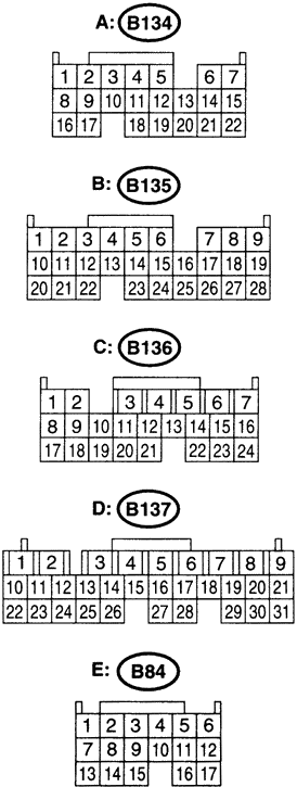
Connector Pin Guide
|

