I would like to put up the standard disclaimers...I do not in any way recommmed or endorse this kit or info, I'm just passing it along for those who have asked. It is designed to quiet an overactive knock sensor, to prevent it from retarding engine timing uneccessarily. Feel free to email me with any questions.

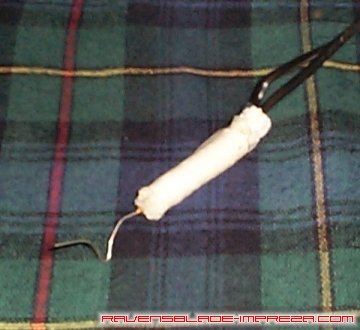
OK, here is the kit as I received it (you also get some nifty directions). It really does not look like much. It isn't. A one foot long piece of wire, two inline wire taps, two resistors, some heat shrink tubing, and (for some unknown reason) rope. So, on with the "reverse engineering."
Ok, upon removing the "MacGuyver Tape," it still looks like something that fell off of a Dodge Omni, but you know it's high tech because we have...yes! Heat shrink tubing!

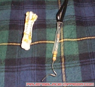
Ok, now that the heat shrink tubing is off, we have a clearer picture of two resistors, the paper clip, a piece of rope (?), and clear heat shrink tubing!

I don't have a good close up, but what we have is two resistors soldered to the two wires and the paper clip. Here's a rough idea of how it all goes together.

The wire labelled "1" would be the "identified" wire (see the instructions below). Wire "2" is the "unidentified" wire. Wire "3" is the paper clip (I'm not kidding). "A" is a resistor, and the color code is as follows: white, brown, yellow, red (910k Ω). "B" is another resistor, and its color code is red, red, orange, gold (22k Ω). Take those color codes with you to Radio Shack and they can find what you need.
This is the Instruction Page, adapted for use here on the web:
The knock sensor is a piezoelectric microphone that is situated on the top of the engine block, approximately seven inches below the bare throttle cable near the back of the intake manifold. It is black in color and shaped like a stack of eight, 3/8 inch size, flat washers. That is to say that it is a doughnut shaped piece, the diameter of a quarter. It is bolted to the engine with one, vertically situated, eight millimeter bolt that is about 40 millimeters long which accepts a 12 mm socket wrench. It has one wire that plugs into a wiring harness just below the throttle cable.
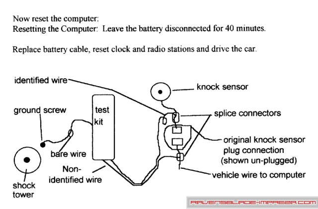
Included in the kit are a circuit with three wires. Two of them are insulated and the third is a bare wire at the opposite end. Each of the two insulated wires will be attached to vehicle wiring with the supplied in line splice connectors. The bare wire wi11 be grounded to the vehicle chassis at a point where other vehicle grounding wires are attached to the chassis. Remove negative, (-), black battery cable from battery terminal. Cover terminal with a rag or paper to reduce the possibility of bumping it with a conductive tool. Working on a non running and cold engine, remove the knock sensor. There is a wire on the knock sensor that has a plug on it. Unplug it from the vehicle's wiring. Now strip the first layer ofinsulation on the knock sensor's wire, near the plug. Strip the metal wire jacket that is around the sensor's wire, starting at the plug, and remove about an inch of this jacket. This metal shield may resemble the shield in a TV cable. The wire conductor that goes from the sensor to the pin in the plug should not be cut or harmed, only the jacket shield is to be stripped back about an inch from the plug to make it ready to receive an in line splice connector from the test kit. The "identified" wire splices onto the knock sensor wire. The unidentified lead splices onto the wire that connects to the other half of the knock sensor wire's plug that is on the vehicle. Attach both of the test kit's wires to the designated car wires with the in line splice connectors. Replace the knock sensor but do not plug it back in. To use the test kit, leave the knock sensor unplugged. (This is a test kit and not intended to be used on the highway as it *may* affect smog controls. However, mine passes emmisions tests WITH the kit in use). Loosen one of the screws that is attaching ground wires to the vehicle at top of the strut
tower of the front left shock absorber. This is near the brake fluid reservoir on a left hand drive vehicle. Insert the bare grounding conductor under this screw and re-tighten the screw.
And this is the installation schematic

Well, that's it for the paper clip anti-hestitaion mod... again, use at your own risk! The good news is, it's completely reversible, and despite the low-tech approach, seems to work quite well!
Standard Disclaimer: Modification of your car involves risks and may void your warranty. I can not be held responsible for the modifications you consciously decide to undertake nor for the results of doing so.
|
|

