This is a basic "how to" on installing an aftermarket Air Fuel Ratio Gauge in your Impreza. You could mount this almost anywhere, however I chose the steering column, so this page will cover an install in that location. You can use these instructions to help you out even if you decide the gauge pack in the center console or the A Pillar is a better place to mount your gauge. This particular Air Fuel Gauge only has three wires- power, ground, and the signal from the oxygen sensor, so hookup was easy. Some may have a fourth wire, which would control illumination of the gauge. Should you have any questions, please feel free to email me and I will try to answer them.
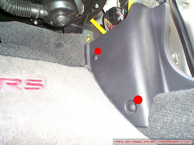
We will start this off with acessing the ECU, located under the passenger side carpet, so that you can wire up your Air Fuel Gauge. The two red dots mark two plastic clips that hold the trim and the carpet in. Pry gently underneath them with a flat headed screwdriver and they will pop right out.
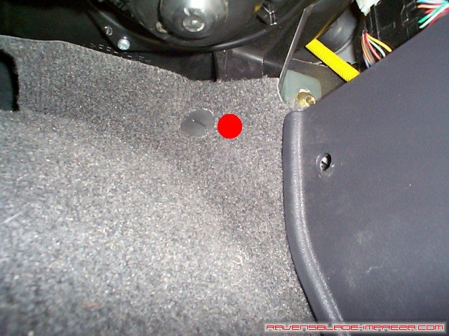
In this picture, you can see one of the posts that hold the carpet up underneath the dash. Wiggle left and right and the carpet will come off of this post.
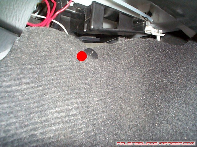
Here is the one along the side of the center console. You can get the carpet off of it in the same manner as before. With that, pull the carpet back towards the passenger seat.
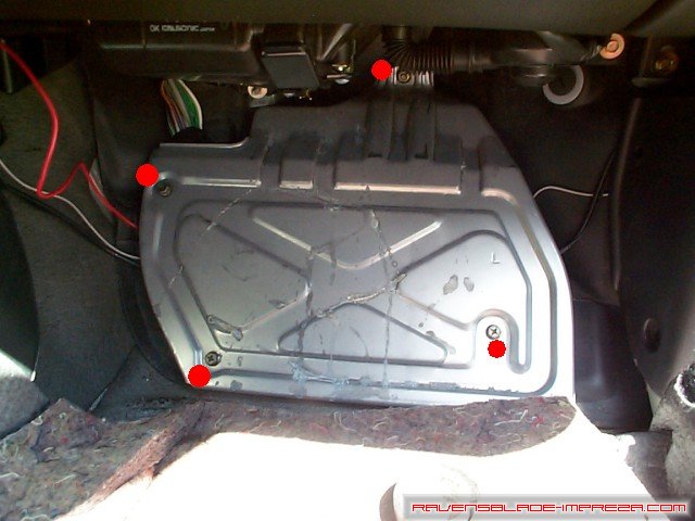
What you see here is the sheild that protects the ECU. The four red dots mark the location of three 10mm bolts and one 10mm nut that hold the shield in place. Remove them to acess the ECU.
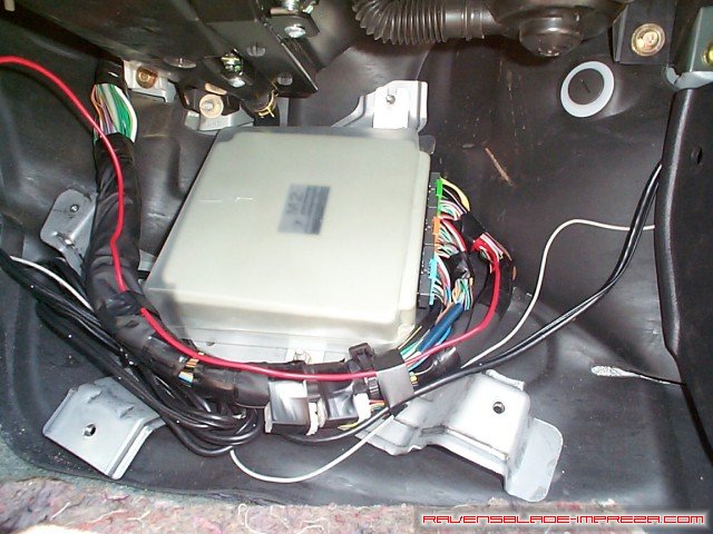
And here we have the ECU and all the wiring harnesses. Remove the plastic cover, and we will get down to business.

This is the ECU as you will see it on a 1999 to 2001 Impreza RS. The 1998 is slightly different, but I do not have a picture of it so this will have to suffice. On the 1999 to 2001 Impreza, the connector you are looking for is the B136 connector, and you are looking for wire #18, which is white- it is located in the middle row, the third wire in from the end. On the 1998 Impreza, you are looking for connector B84 and wire #24 and it should be yellow/blue- it will be in the second row, and be wire number 7 in from the end. WRX owners, you are looking for pin 17 on connector B135 (the only 28 pin connector on your ECU), which is a white wire. It is the third pin in from the end in the middle row of B135. If you need a bit of help on which is which, visit the wiring guides page and take a look at the ECU pinouts for your model year.
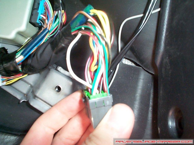
Remove the electrical tape from the loom and find your wire and isolate it from the bunch in the harness. I simply used a "vampire" tap to splice in an extension wire which runs from the ECU to the area under the steering column. Tap for this about 2 or 3 inches down from the connector, so that there is room to reconnect the harness to the ECU.
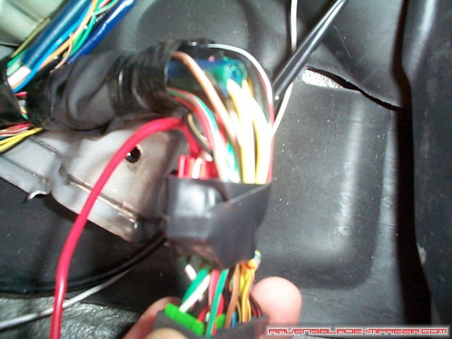
With the O2 signal wire tapped, tape back up the wiring loom, and then plug the connector back into the ECU. With that, run your wire over towards the driver's side of the car and up into the area under the radio. Replace the plastic cover, metal shield, and finally the carpet and trim on the passenger's side.
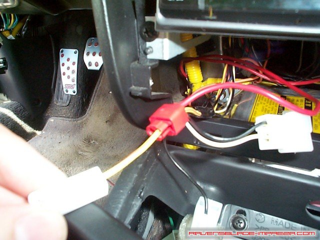
I wanted a source of power that was switched off of the ignition, and the power to the cigarette lighter is a very good place to grab power from. If you pull off the trim piece around the radio, there will be lots of room to work. On my 2000, there is one wire for power and a seperate harness for ground to the cigarette lighter, so it was easy to find the correct wire and run an extension from it to the area under the steering colum as well. While you are in the center console, pull the extension wire from the ECU through the center console and over to the area under the steering column.
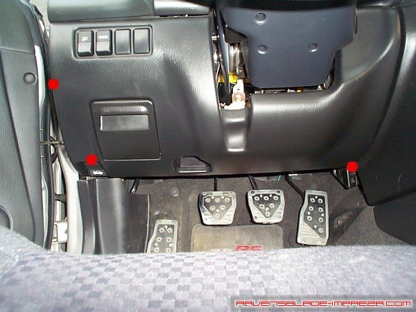
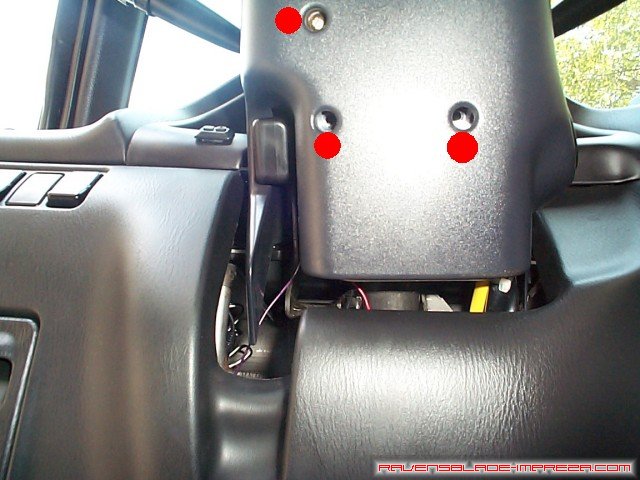
Now, to remove the trim under the steering column. In this picture, you can see the plastic trim panel that covers the area in question. The three red dots mark the approximate location of the fasteners holding this piece on; 2 screws and one plastic trim plug. In addition to these 3 fasteners, there are two 'clips' on either side of the opening for the steering wheel. These will just pull right out once the three fasteners are removed.
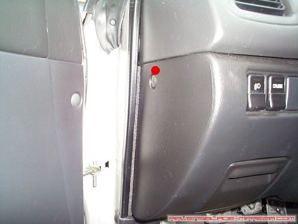
In this picture, you can see the plastic trim plug's location (right next to the red dot). You need to put a phillips (+) headed screwdriver in and turn about 1/4 of a turn. The center piece will pop up a little bit, and you can pull it out. Gently tug on the remaining outside piece, and it will come right out.
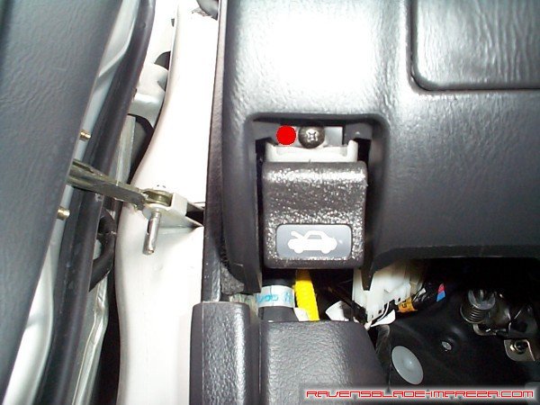
In this picture, you see one of the two screws, right by the pull for the hood release. Just unscrew that and put it aside.
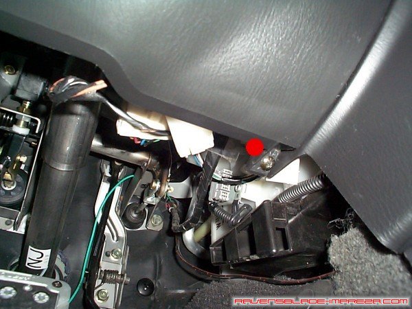
The red dot marks the location of the second screw holding the dash trim on. Unscrew this last screw, and then pull the whole sheet of plastic out towards the driver's seat gently. Be careful! The harnesses for the foglights, cruise control, and the OBD-II diagnostic port all are attached to the plastic!
With that out of the way, you will need to remove the covering on the steering column. Looking up from below, you will see the three screws that hold the lower column cover on (I have two removed in the photo) which I have marked with red dots.
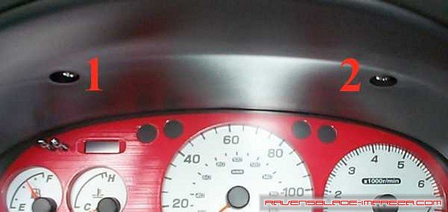
With that done, you will need to remove the cowling on the gauge area in order to get the top column cover off. It is only held in by two screws, marked 1 and 2. With those removed, drop the steering column as low as it will go, and remove this cowling. Now you should be able to pull the top column cover straight up and off.
I'm going to skip ahead a bit here, as what course you take is primarily up to you from here. I got a pair of gauge cups made by Autometer from Summit Racing (as well as the Air Fuel Gauge) which I placed in an appropriate place for me on the top column cover and screwed them in. I placed them in a location that allowed me to still see most of what was going on with the stock gauge cluster. As every gauge cup will be different, I'm not going to cover the gauge cup portion of the install- the instructions that come with the cup will lead you in the right direction.
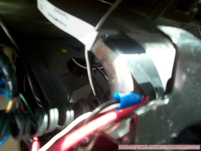
From here, it's a simple matter of hooking things up- wire the + lead from the gauge to the extension run off of the cigarette lighter, the sensor wire (mine was purple) to the extension from the O2 sensor wire on the ECU, and then find a good metal ground. I added one a long time ago that is screwed into the metal beam right in front of your left knee if you were sitting in the driver's seat, so I just tapped into that- you can see it in the picture above. Use either "vampire" taps, solderless crimp connectors, or solder and tape to solid connections. Test things before putting the dash back together- if it doesn't work at all, the most likely cause is a bad ground, so check there first. If everything is working, put the dash back together in reverse order; top cover, cowl, bottom cover, and then the big trim piece.
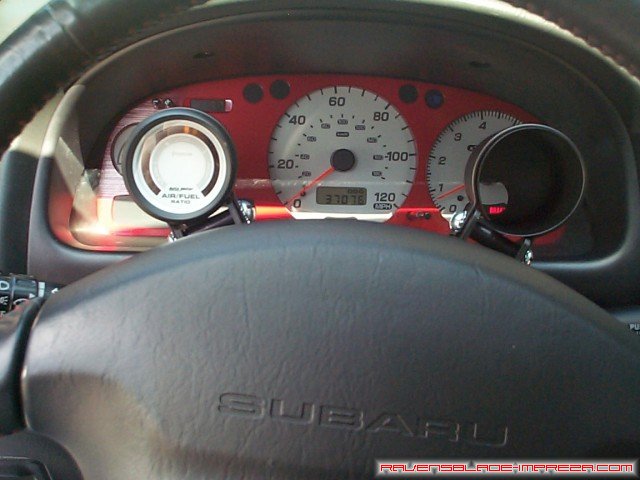
So there it is, done. I have an EGT gauge that still has not come in yet waiting to take up residency in the right hand pod, but I really like the placement- it keeps all the important gauges in one place. When I am driving, I can still see the entire fuel gauge, the top half of the water temperature, the entire speedometer, and from zero to about 7000rpm on the tachometer. There will be a pod just above the stock cluster on the dashboard for oil temperature, oil pressure, and boost/vaccuum... well, someday soon.
Standard Disclaimer: Modification of your car involves risks and may void your warranty. I can not be held responsible for the modifications you consciously decide to undertake nor for the results of doing so.
|
|
